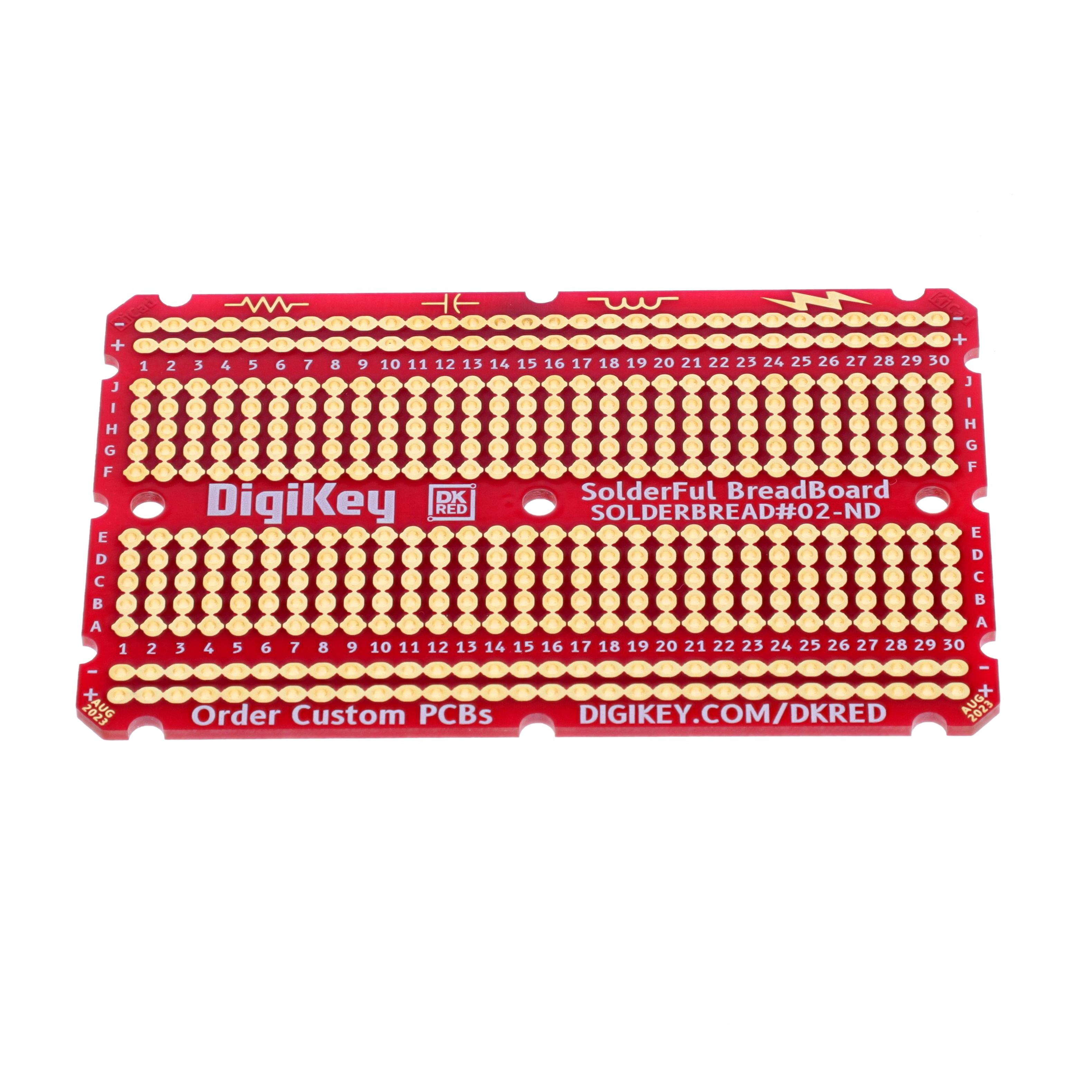
Mfr Part # DKS-SOLDERBREAD-02
BREADBOARD GENERAL PURPOSE PTH
DigiKey Standard
License: See Original Project ESP32
Okay, confession time. I've been slacking on keeping track of my kids' heights. You know, the classic doorframe lines? I haven't gotten to do that. I’ve just moved around too much, but I'm an engineer, so I decided to build a digital growth chart. It is not just going to be any growth chart; this thing is going to be automated, track heights in a spreadsheet, be fun for the kids, and have a few other surprises.
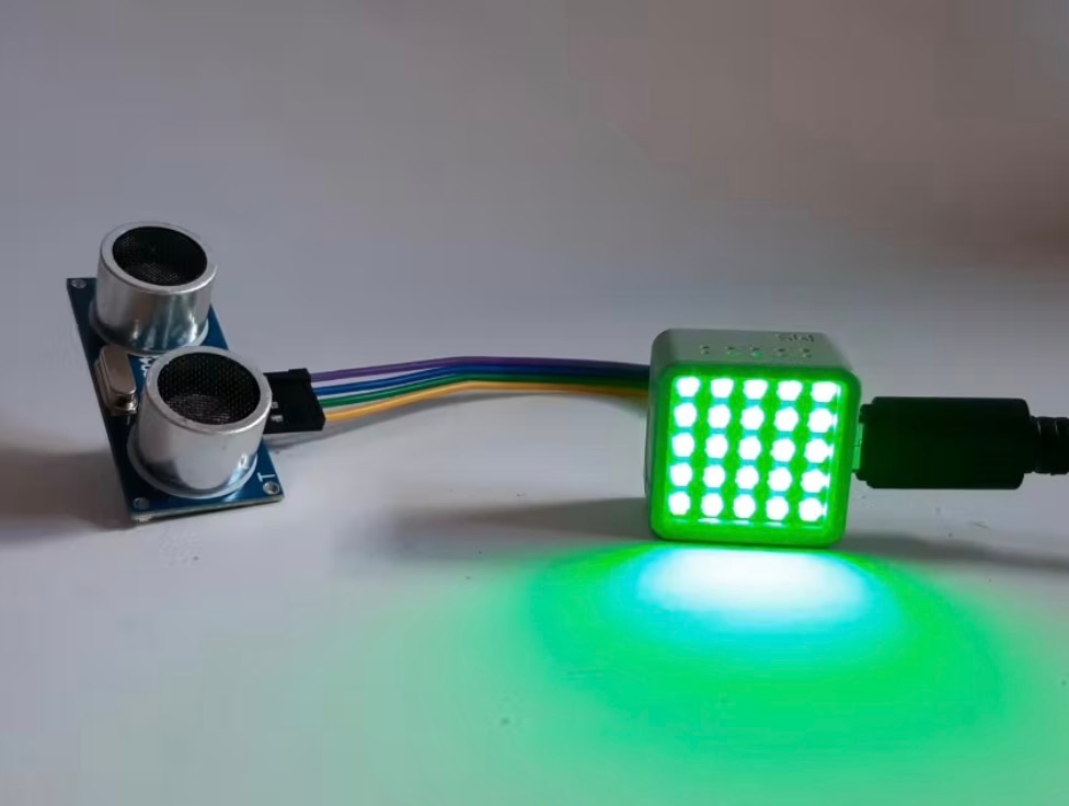
Here's my crazy vision: an automated growth chart that measures heights, logs it in a spreadsheet, has a button that sends pictures to the grandparents, and I should throw in some addressable RGB LEDs and a thermal printer for good measure, right? The plan was simple (or so I thought). I’ll use some aluminum extrusion as the backbone, a sliding carriage with V-wheels, and a rotary encoder to measure the movement, kind of like a 3D printer extruder, but in reverse. I’ll use a small LiPo battery, an ESP32 WiFi microcontroller with a camera, and some perf board to tie it all together.
First, I’ll work on the mechanical stuff. In order to measure height, I used some GT2 belts, a pulley, and an off-the-shelf metal bracket that I modified by enlarging a hole to mount the rotary encoder to the carriage. The encoder sits between the two V-wheels to maintain a good connection with the encoder as it spins. I attached the carriage to the aluminum extrusion, threaded through the belt, and got the encoder spinning as the carriage moved up and down. This will spit out pulses that the microcontroller can read.
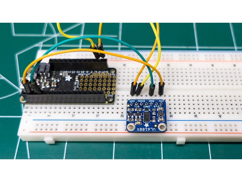
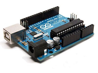
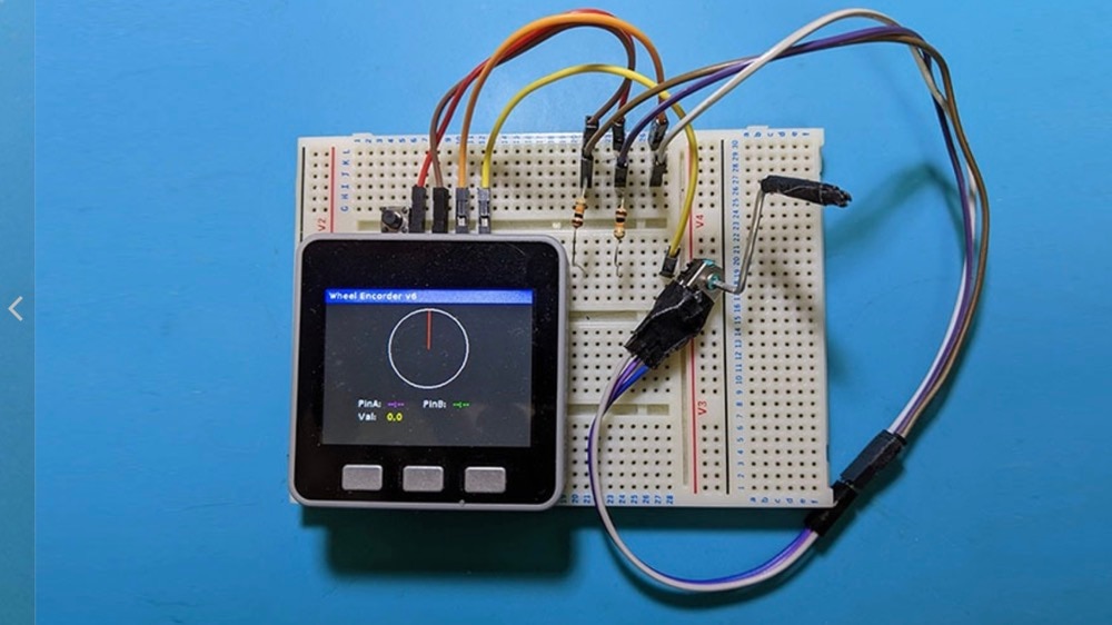
Next, I decided to work on the electronics. I soldered the encoder and the microcontroller to a piece of perf board. I used some short lengths of wire to connect them and wrote some Arduino code to read the encoder pulses. I did the math to convert the 2mm pitch of the GT2 belt to length measurements. I added a passive RC low-pass filter and also incorporated some software debouncing to smooth things out even more. I tested the software and encoder by sliding the carriage up and down the extrusion, and it worked! Well, sort of... The count went up and down as I spun the encoder, but I noticed that the numbers didn’t match. The counts were all over the place. It would lose pulses, which would give me inaccurate readings, totally unacceptable for this project. I need accuracy! I spent a few days tweaking, coding, and getting frustrated. I had to admit defeat. The mechanical rotary encoder just wasn't cutting it. I think I picked the wrong component. It is just too noisy and too unreliable. It was fine for projects like volume knobs and menu selections, but not for precise measurements.
It was time for a pivot. I dug through my parts bin and found an optical rotary encoder. It doesn’t use mechanical switches, just clean optical signals. I hooked it up, tweaked my code, and…it worked like a charm! It was accurate, reliable, and had way more resolution. However, there was a catch. It was bigger than the other encoder, so I had to redesign the entire carriage mount. I went back to the drawing board to rethink the mount. I designed a new carriage plate in my 3D modeling software, and then I laser-cut it out of some 3mm plywood for a quick test, and it fit perfectly. I like to use laser cutting for testing out the layout and hole spacing. It is much faster than 3D printing. Now that I know the spacing is correct, I could update my design with a 3D-printed enclosure to house all the electronics.
I modeled the enclosure, added mounting features for the microcontroller, and even designed a snap-in battery holder. I did have one minor oversight: I forgot a power button, but a quick drill job fixed that problem. Now, it was time for assembly. I transferred all the components to the 3D-printed enclosure, soldered the encoder wires, and even printed some button extensions to make the buttons easier to push when it is in the enclosure. Now I just needed to mount it on the wall. I 3D-printed some adjustable mounts to make it easier to get the growth chart exactly 500mm off the ground, which is the starting position. After some measurements, some minor adjustments, and some belt trimming, it was ready.
It was time for the moment of truth. I will measure my own height. My license says I'm 5' 9". Let's see… measuring… 5' 9.07"! Unbelievable! I was spot-on. What’s more, I could have been rounding up this whole time! I’m gonna start telling people I’m 5’10”!
I couldn't believe how well it worked. All that time wasted on the mechanical encoder! The optical encoder was the answer all along. But this is just the beginning. I still plan on adding all the bells and whistles to this project. I need to add the RGB lights, the thermal printer, and, most importantly, the camera to send pictures to the grandparents! That's all coming in part two. Stay tuned!