Mfr Part # 5249
MEMORY CARD MICROSD 64MB CLASS 4
Adafruit Industries LLC
License: See Original Project LED Matrix Raspberry Pi SBC
Courtesy of Adafruit
Guide by John Park
Overview
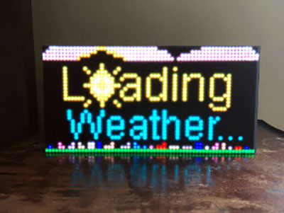
Note: there's no flicker in real life, these are just difficult to film!
Build a wall mounted arcade that's a low-resolution work of art! You can play PICO-8 games on it or just run sweet demoscene code for a retro-tech bit of eye candy.
This project uses a Raspberry Pi 5 running Piomatter to drive a 128x128 pixel display made of four RGB LED matrices. A deep frame from IKEA plus some 3D printed brackets makes it straightforward to assemble.
The way this works is that PICO-8 is launched against XVFB (a virtual X framebuffer) so it thinks it's running on a really tiny monitor. But in reality, a python script (virtualdisplay.py) will grab that framebuffer and feed it to the LED matrices via Piomatter.
Parts
Frame
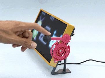
SANNAHED frame from IKEA. It comes in a few colors to match your decor.
PICO-8 Fantasy Console
The PICO-8 Fantasy Console cost about $15. This includes all future versions and is cross-platform so you can install it on your Windows, Mac, Linux, and Raspberry Pi machines.
Controllers
You'll want some generic wired USB gamepads such as these SNES-styled ones.
Or you can go with some wireless Bluetooth gamepads such as these.
Printed Brackets
Print the models attached below on an FDM printer using PLA or PETG. You'll need the following multiples:
bracket x1
speaker x1
tri-corner_pi x1
tri-corner x3
jointA x2
jointB x2
corner x4
You can print them yourself or send them to a 3D printing service.
Build the Arcade
Panel Arrangement
There are currently two supported arrangements for four 64x64 panels in Piomatter --serpentine and --no-serpentine
No-Serpentine
In this arrangement all four panels are oriented alike.
The benefit of this is that view-dependent differences in pixel color are a non-issue.
However, a rather long run of IDC ribbon cable is required to make the connection from panel 2's output to panel 3's input, approximately 50cm for a 3mm pitch matrix panel.
If you have a long enough cable, go for this arrangement.
Serpentine
In serpentine arrangement, the two bottom panels are oriented upside down.
The benefit of this arrangement is shorter cable runs.
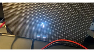
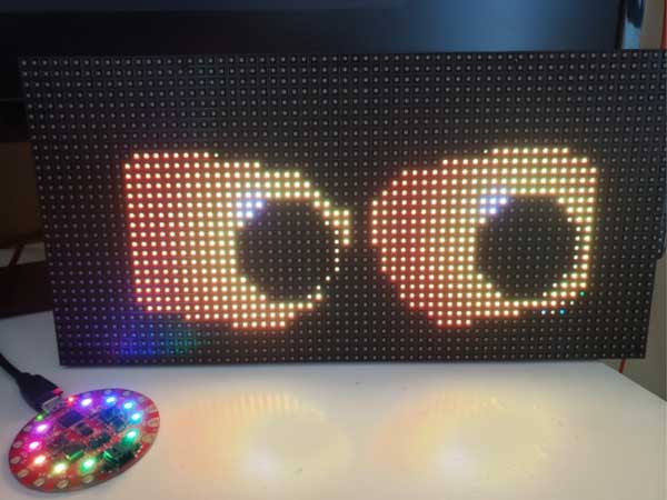
The downside is that there are view-angle dependent color shifts visible between the upper and lower pairs, particularly when lighter colors span the break, which can cause a blueish line to appear.
In the attached screen photos, you can see the cause of this is the physical arrangement of the RGB LED trio per pixel. Blue is at the bottom of the pixel, so it is perceptually stronger where the two bottom rows meet.
The build in this guide uses serpentine arrangement since I didn't have a 50cm cable on hand.
Connector Bracket
Plug in the IDC cables and then mount the back bracket.
Press the bracket onto the panels so the registration pegs are nicely seated, then screw the bracket into place using M3 screws.
Note, the bracket is designed to accommodate both panel arrangements, so there are holes that will remain un-used -- check for brass threading before screwing into a given hole.
Edge Joints
Next, screw in the edge joints to align and secure the panel edges. Note that the side joints (printed in magenta filament here) have cutouts in them to accommodate the data sockets.
Matrix Bonnet
Follow the silkscreen polarity markings and screw in the two sets of power cables to the terminal block as shown here.
Pi Mount
Use four M2.5 screws and nuts to create mounting points for the Pi 5.
Fasten the Pi with nuts or short standoffs so that the Matrix Bonnet can still be connected.
Mount Pi to Panel
Plug in the IDC cable from the Matrix Bonnet to the input of panel 1.
Screw in the Pi tri-corner mount to the panel.
Then, screw in the other tri-corner mounts. The keep the display centered in the frame, along with the frame spacer.
Plug in the four power connectors.
Frame Mounting
Place the acrylic panel in the front of the frame.
Set the four corner spacers into place as shown, so the wooden frame spacer will seat into them and hold them flush to the front of the frame.
Carefully place the matrix display into the center of the frame.
Speaker Prep
Press fit the speaker into the printed speaker holder.
Fit the speaker into the frame, then plug the USB cable into the Raspberry Pi.
Two Power Supplies
Plug in the USB C power to the Pi and the 5V center-positive 10A DC power cable to the Matrix Bonnet.
Back Panel
Dress the cables to exit below the panel 1 corner, then cut out a little mouse hole in the back panel for them using a hobby knife.
Pi Setup & Code
For the initial setup, follow this excellent guide, RGB Matrix Panels with Raspberry Pi. Make sure you can get the virtual display running as shown on this page, this is the same method we'll use to display Pico-8.
RGB Matrix Panels with Raspberry Pi 5
By Tim C
You'll want to follow the instructions for using SSH since the setup will eventually be headless, in case you need to make adjustments after you've mounted the arcade to the wall.
Pico-8
Next, download and install Pico-8 from the download page. There is a small cost, but that helps the developers, and you get all future updates.
Setting Up Pico-8
You'll need to first create a login.
Download the .zip, un-compress it, and move the pico-8 directory to your user directory. The path should look like this:
/home/admin/pico-8
Execute
We'll run the 64-bit version of Pico-8. To make it executable, open a command line, navigate to the pico-8 directory by typing cd ~/pico-8 and press Enter.
Then, make pico_64 executable by typing:
chmod -x ./pico8_64
List the directory contents with ls -l to see the permissions have changed.
Now, you can launch Pico-8 by typing:
./pico8_64
This won't launch to your matrix display, but you should see it on your HDMI display if it's plugged in. You can try it out and play around a bit. When you're done you can press ctrl-q to quit.
Peripherals
This is a good time to add the audio and gamepads to the setup.
Sound
Plug in the mini external USB stereo speaker to a USB port on the Raspberry Pi 5. It seems to "just work" on reboot, but you can check out this guide for details on configuration. Try running Pico8_64 to make sure you hear sound.
Gamepad
Plug in your gamepad or gamepads to USB. These, too, should just work after a reboot. However, some extra configuration may be necessary for Pico-8 to use the proper button mapping.
This page is an excellent resource for determining controller configuration and updating the sdl_controllers.txt file.
Here’s what the string looks like for my generic USB SNES-style gamepads:
030000001f08000001e4000006010000,USB gamepad gp100,platform:Linux, X,a:b2,b:b1,x:b3,y:b0,back:b8,start:b9,leftshoulder:b4,rightshoulder:b5,dpup:-a1,dpdown:+a1,dpleft:-a0,dpright:+a0,
What about wireless? You can use Bluetooth controllers directly with Raspberry Pi 5 or 2.4GHz controllers with a dongle, such as those provided with some 8BitDo controllers. Once paired/trusted/connected to the system, follow the same instructions as above to configure specific button mapping.
Virtual Display
Now we can set it up to send the Pico-8 display to the LED matrix.
From the RGB Matrix Panels with Raspberry Pi 5 guide we saw that we can mirror an application to the LED matrix using the Python virtualdisplay.py script. This is one of the example scripts that was automatically installed along with Piomatter.
First, activate the virtual environment:
source ~/venvs/blinka_venv/bin/activate
Copy and paste the command shown here to launch the script and pico8_64 as the mirrored app. The flag -splore will tell Pico-8 to launch into SPLORE which is a sort of kiosk/console mode perfect for using just a game controller to explore and launch games without keyboard and mouse.
python /home/admin/Adafruit_Blinka_Raspberry_Pi5_Piomatter/examples/virtualdisplay.py --brightness 0.5 --pinout AdafruitMatrixBonnet --backend xvfb --width 128 --height 128 --serpentine --num-address-lines 5 --num-planes 6 -- ~/pico-8/pico8_64 -splore
You should see Pico-8 on the LED matrix display now! When you're done playing with it you can quit with a ctrl-c.
You can experiment with different --brightness levels from 0.0 to 1.0 and --num-planes from 1-10 in order to get the best, flicker-free look.
Autorun on Boot
Since we'll use the arcade in headless mode, we want to set it up to automatically launch the virtualdisplay.py script on startup.
Shell Script
To do this, we'll first create a shell script and then we'll set it to automatically launch on startup.
Copy the script below and save it to your home directory as start_pico8_splore_matrix.sh.
#!/bin/bash

# Add logging
exec > /home/admin/pico8_startup.log 2>&1

echo "Starting script at $(date)"

# Activate the Python virtual environment
echo "Activating virtual environment"
source /home/admin/venvs/blinka_venv/bin/activate
echo "Virtual environment activated: $VIRTUAL_ENV"

# Run the virtual display with PICO-8
echo "Starting virtual display and PICO-8"
python /home/admin/Adafruit_Blinka_Raspberry_Pi5_Piomatter/examples/virtualdisplay.py --brightness 0.5  --pinout AdafruitMatrixBonnet --backend xvfb --width 128 --height 128 --serpentine --num-address-lines 5 --num-planes 6 -- ~/pico-8/pico8_64 -splore

echo "Script completed at $(date)"
#!/bin/bash - This is the "shebang" line that identifies this as a bash script
exec > /home/admin/pico8_startup.log 2>&1 - This redirects all output (both standard output and errors) to a log file at the specified path
echo "Starting script at $(date)" - Logs the start time of the script
source /home/admin/venvs/blinka_venv/bin/activate - Activates the Python virtual environment
The main command runs a Python script called virtualdisplay.py with several parameters:
After -- the script specifies what to run on the virtual display: ~/pico-8/pico8_64 -splore, which launches the 64-bit version of PICO-8 in "splore" mode
echo "Script completed at $(date)" - Logs the completion time of the script
You can test this script now before we have it auto-run. Make it executable by typing:
chmod +x ~/start_pico8_splore_matrix.sh
Crontab
The crontab can be used to create a cron job that runs our bash script at startup.
Type this in the terminal to launch the crontab editor:
crontab -e
Then add this line:
@reboot /bin/bash ~/start_pico8_splore_matrix.sh
Then save by pressing ctrl-s and close the editor by pressing ctrl-x.
Moment of Truth
OK, let's see if it worked! Restart the system by typing:
sudo reboot
You should see the Raspberry Pi restart and after about 20 seconds, Pico-8 will start up on the matrix display!
Mount and Play
A simple wall hook is all you need to mount the arcade to the wall.
As a bonus, use a cord cover kit to neaten up the wiring.
Build one for every room or give them out as gifts!