Mfr Part # 5797
GRAPHIC DISPLAY TFT RGB 3.2"
Adafruit Industries LLC
License: See Original Project 3D Printing Displays LCD / TFT LEDs / Discrete / Modules Arduino
Courtesy of Adafruit
Guide by by Ruiz Brothers and 2 other contributors
Overview
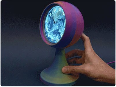
Build a miniature fireplace that plays Yule Log video clips using an Adafruit Qualia ESP32-S3 and a 3.2" rectangle bar TFT display.
Load a series of your favorite video files on a micro-SD card and display them on the long TFT bar screen. Cycle through them by touching the screen.
3D print the parts to secure the display, Qualia ESP32-S2, and micro SD breakout. The fireplace mantel is decorative and swappable so you can customize it.
Parts
Rectangle Bar RGB TTL TFT Display - 3.2" 320x820 with Cap Touch
Adafruit Micro SD SPI or SDIO Card Breakout Board - 3V ONLY!
SD/MicroSD Memory Card (8 GB SDHC)
6 x M2.5x5mm Screws
Prerequisite Guides
Take a moment to review the following guides to learn more about the products.
Text editor powered by tinymce.
Circuit Diagram
The diagram below provides a general visual reference for wiring of the components once you get to the Assembly page. This diagram was created using the software package Fritzing.
Adafruit Library for Fritzing
Adafruit uses the Adafruit's Fritzing parts library to create circuit diagrams for projects. You can download the library or just grab individual parts. Get the library and parts from GitHub - Adafruit Fritzing Parts.
Wired Connections
The Qualia ESP32-S3 is powered by a 5V 1A USB power supply.
SCK from Qualia S3 to CLK on Micro SD
MISO from Qualia S3 to SO on Micro SD
MOSI from Qualia S3 to SI on Micro SD
CS from Qualia S3 to CS on Micro SD
A1 from Qualia S3 to DAT2 on Micro SD
A0 from Qualia S3 to D1 on Micro SD
3.3V from Qualia S3 to 3V on Micro SD
GND from Qualia to GND on Micro SD
Text editor powered by tinymce.
Converting Videos
Video File Preparation
You'll want to use a video file in a common format such as H.264 (.MP4 or .MOV) with a duration of anywhere from 10 seconds to 3 minutes in length. Your video clip should ideally have a 16:9 aspect ratio (such as 1920 x 1080 or 1280 x 720). Note: the final video ratio will be ~2.6:1, so there will be some cropping off the top and bottom.
The 3.2" display has a screen resolution of 320x820
Online Converter
You can use the website linked below to convert your video file into MJPEG. (maximum file size is 100MB.)
Click on the Choose Files icon. Navigate to your video file and click Open. Click on the dropdown icon and select MJPEG under the video section. Then, click on the gear icon to open the settings dialog.
Use the following settings for best playback performance.
Codec: MJPEG
Quality: Highest
Resize: Custom / 320 x 820
Resize Method: Zoom and crop
Frame rate : 12 FPS
Rotate: Rotate by 90 degrees counterclockwise
Click on the Convert button when finished.
Format SD
Format a micro-SD card to FAT32.
Create VIDEOS folder
Make a new folder in the SD card and name it VIDEOS.
Conversion Completed
Click the Download button when the upload and conversion is complete.
Use the VLC media player app to playback the video for reviewing.
Rename the video file so it only contains the .MJPEG extension. Then, drag and drop it into the VIDEOS folder on the micro-SD card.
Mac users may need to delete .DS files inside the VIDEOS folder
Text editor powered by tinymce.
CAD Files
3D Printed Parts
STL files for 3D printing are oriented to print "as-is" on FDM style machines. Parts are designed to 3D print without any support material using PLA filament. Original design source may be downloaded using the links below.
Parts List
button-qualia.stl
case-cover.stl
case-tft.stl
modern-fireplace-base.stl
modern-fireplace.stl
qualia-tft-mount.stl
victorian-fireplace.stl
victorian-platform.stl
Build Volume
The parts require a 3D printer with a minimum build volume.
150mm (X) x 150mm (Y) x 84mm (Z)
Design Source Files
The project assembly was designed in Fusion 360. This can be downloaded in different formats like STEP, STL and more. Electronic components like Adafruit's boards, displays, connectors and more can be downloaded from the Adafruit CAD parts GitHub Repo.
Text editor powered by tinymce.
Install Bootloader
The Qualia ESP32-S3 microcontroller ships running a circular rainbow gradient example for the round 480x480 display. It's lovely, but you probably had other plans for the board. As you start working with your board, you may want to return to the original code to begin again, or you may find your board gets into a bad state. Either way, this page has you covered.
You're probably used to seeing the TFT_S3BOOT drive when loading CircuitPython or Arduino. The TFT_S3BOOT drive is part of the UF2 bootloader, and allows you to drag and drop files, such as CircuitPython. However, on the ESP32-S3 the UF2 bootloader can become damaged.
Factory Reset Firmware UF2
If you have a bootloader still installed - which means you can double-click to get the TFT_S3BOOT drive to appear, then you can simply drag this UF2 file over to the BOOT drive.
To enter bootloader mode, plug in the board into a USB cable with data/sync capability. Press the reset button once, wait till the RGB LED turns purple, then press the reset button again. Then drag this file over:
Qualia S3 RGB-666 Factory Reset
Your board is now back to its factory-shipped state! You can now begin again with your plans for your board.
Factory Reset and Bootloader Repair
What if you tried double-tapping the reset button, and you still can't get into the UF2 bootloader? Whether your board shipped without the UF2 bootloader, or something damaged it, this section has you covered.
There is no bootloader protection for the UF2 bootloader. That means it is possible to erase or damage the UF2 bootloader, especially if you upload an Arduino sketch to an ESP32-S2/S3 board that doesn't "know" there's a bootloader it should not overwrite!
It turns out, however, the ESP32-S2/S3 comes with a second bootloader: the ROM bootloader. Thanks to the ROM bootloader, you don't have to worry about damaging the UF2 bootloader. The ROM bootloader can never be disabled or erased, so it’s always there if you need it! You can simply re-load the UF2 bootloader from the ROM bootloader.
Completing a factory reset will erase your board's firmware which is also used for storing CircuitPython/Arduino/Files! Be sure to back up your data first.
There are two ways to do a factory reset and bootloader repair. The first is using WebSerial through a Chromium-based browser, and the second is using esptool via command line. We highly recommend using WebSerial through Chrome/Chromium.
The next section walks you through the prerequisite steps needed for both methods.
Download .bin and Enter Bootloader
Step 1. Download the factory-reset-and-bootloader.bin file
Save the following file wherever is convenient for you. You will need to access it from the WebSerial ESPTool.
Note that this file is approximately 3MB. This is not because the bootloader is 3MB, it is because the bootloader is near the end of the available flash. Most of the file is empty but it’s easier to program if you use a combined file.
Qualia S3 RGB-666 Factory Reset .bin File
Step 2. Enter ROM bootloader mode
Entering the ROM bootloader is easy. Complete the following steps.
Before you start, make sure your ESP32-S2/S3 is plugged into USB port to your computer using a data/sync cable. Charge-only cables will not work!
To enter the bootloader:
Press and hold the BOOT/DFU button down. Don't let go of it yet!
Press and release the Reset button. You should still have the BOOT/DFU button pressed while you do this.
Now you can release the BOOT/DFU button.
No USB drive will appear when you've entered the ROM bootloader. This is normal!
Now that you've downloaded the .bin file and entered the bootloader, you're ready to continue with the factory reset and bootloader repair process. The next two sections walk you through using WebSerial and esptool.
The WebSerial ESPTool Method
We highly recommend using WebSerial ESPTool method to perform a factory reset and bootloader repair. However, if you'd rather use esptool via command line, you can skip this section.
This method uses the WebSerial ESPTool through Chrome or a Chromium-based browser. The WebSerial ESPTool was designed to be a web-capable option for programming ESP32-S2/S3 boards. It allows you to erase the contents of the microcontroller and program up to four files at different offsets.
You will have to use a Chromium browser (like Chrome, Opera, Edge...) for this to work, Safari and Firefox, etc. are not supported because we need Web Serial and only Chromium is supporting it to the level needed.
Follow the steps to complete the factory reset.
If you're using Chrome 88 or older, see the Older Versions of Chrome section at the end of this page for instructions on enabling Web Serial.
Connect
You should have plugged in only the ESP32-S2/S3 that you intend to flash. That way there's no confusion in picking the proper port when it's time!
In the Chrome browser visit https://adafruit.github.io/Adafruit_WebSerial_ESPTool/. You should see something like the image shown.
Press the Connect button in the top right of the web browser. You will get a pop up asking you to select the COM or Serial port.
Remember, you should remove all other USB devices so only the ESP32-S2/S3 board is attached, that way there's no confusion over multiple ports!
On some systems, such as MacOS, there may be additional system ports that appear in the list.
The JavaScript code will now try to connect to the ROM bootloader. It may timeout for a bit until it succeeds. On success, you will see that it is Connected and will print out a unique MAC address identifying the board along with other information that was detected.
Once you have successfully connected, the command toolbar will appear.
Erase the Contents
This will erase everything on your board! If you have access, and wish to keep any code, now is the time to ensure you've backed up everything.
To erase the contents, click the Erase button. You will be prompted whether you want to continue. Click OK to continue or if you changed your mind, just click cancel.
You'll see "Erasing flash memory. Please wait..." This will eventually be followed by "Finished." and the amount of time it took to erase.
Do not disconnect! Immediately continue on to programming the ESP32-S2/S3.
Do not disconnect after erasing! Immediately continue on to the next step!
Program the ESP32-S2/S3
Programming the microcontroller can be done with up to four files at different locations, but with the board-specific factory-reset.bin file, which you should have downloaded under Step 1 on this page, you only need to use one file.
Click on the first Choose a file.... (The tool will only attempt to program buttons with a file and a unique location.) Then, select the *-factory-reset.bin file you downloaded in Step 1 that matches your board.
Verify that the Offset box next to the file location you used is (0x) 0.
Once you choose a file, the button text will change to match your filename. You can then select the Program button to begin flashing.
A progress bar will appear and after a minute or two, you will have written the firmware.
Once completed, you can skip down to the section titled Reset the Board.
The esptool Method (for advanced users)
If you used WebSerial ESPTool, you do not need to complete the steps in this section!
Once you have entered ROM bootloader mode, you can then use Espressif's esptool program to communicate with the chip! esptool is the 'official' programming tool and is the most common/complete way to program an ESP chip.
Install ESPTool.py
You will need to use the command line / Terminal to install and run esptool.
You will also need to have pip and Python installed (any version!).
Install the latest version using pip (you may be able to run pip without the 3 depending on your setup):
pip3 install --upgrade esptool
Then, you can run:
esptool.py
Make sure you are running esptool v3.0 or higher, which adds ESP32-S2/S3 support.
Test the Installation
Run esptool.py in a new terminal/command line and verify you get something like the below:
Connect
Run the following command, replacing the identifier after --port with the COMxx, /dev/cu.usbmodemxx or /dev/ttySxx you found above.
esptool.py --port COM88 chip_id
You should get a notice that it connected over that port and found an ESP32-S2/S3.
Erase the Flash
Before programming the board, it is a good idea to erase the flash. Run the following command.
esptool.py erase_flash
You must be connected (by running the command in the previous section) for this command to work as shown.
Installing the Bootloader
Run this command and replace the serial port name with your matching port and the file you just downloaded
esptool.py --port COM88 write_flash 0x0 tinyuf2_combo.bin
Don't forget to change the --port name to match.
Adjust the bootloader filename accordingly if it differs from tinyuf2_combo.bin.
There might be a bit of a 'wait' when programming, where it doesn't seem like it's working. Give it a minute, it has to erase the old flash code which can cause it to seem like it's not running.
You'll finally get an output like this:
Once completed, you can continue to the next section.
Reset the board
Now that you've reprogrammed the board, you need to reset it to continue. Click the reset button to launch the new firmware.
If you have a 480x480 round display plugged in, you should see a circular rainbow gradient appear on the display.
You've successfully returned your board to a factory reset state!
Older Versions of Chrome
As of chrome 89, Web Serial is already enabled, so this step is only necessary on older browsers.
We suggest updating to Chrome 89 or newer, as Web Serial is enabled by default.
If you must continue using an older version of Chrome, follow these steps to enable Web Serial.
If you receive an error like the one shown when you visit the WebSerial ESPTool site, you're likely running an older version of Chrome.
You must be using Chrome 78 or later to use Web Serial.
To enable Web Serial in Chrome versions 78 through 88:
• Visit chrome://flags from within Chrome.
• Find and enable the Experimental Web Platform features
• Restart Chrome
The Flash an Arduino Sketch Method
This section outlines flashing an Arduino sketch onto your ESP32-S2/S3 board, which automatically installs the UF2 bootloader as well.
Arduino IDE Setup
If you don't already have the Arduino IDE installed, the first thing you will need to do is to download the latest release of the Arduino IDE. ESP32-S2/S3 requires version 1.8 or higher. Click the link to download the latest.
After you have downloaded and installed the latest version of Arduino IDE, you will need to start the IDE and navigate to the Preferences menu. You can access it from the File > Preferences menu in Windows or Linux, or the Arduino > Preferences menu on OS X.
The Preferences window will open.
In the Additional Boards Manager URLs field, you'll want to add a new URL. The list of URLs is comma separated, and you will only have to add each URL once. The URLs point to index files that the Board Manager uses to build the list of available & installed boards.
Copy the following URL.
https://raw.githubusercontent.com/espressif/arduino-esp32/gh-pages/package_esp32_dev_index.json
Add the URL to the Additional Boards Manager URLs field (highlighted in red below).
Click OK to save and close Preferences.
In the Tools > Boards menu you should see the ESP32 Arduino menu. In the expanded menu, it should contain the ESP32 boards along with all the latest ESP32-S2 boards.
Now that your IDE is setup, you can continue on to loading the sketch.
Load the Blink Sketch
In the Tools > Boards menu you should see the ESP32 Arduino menu. In the expanded menu, look for the menu option for the Adafruit Qualia ESP32-S3 RGB666, and click on it to choose it.
Open the Blink sketch by clicking through File > Examples > 01.Basics > Blink.
Once open, click Upload from the sketch window.
Once successfully uploaded, the little red LED will begin blinking once every second. At that point, you can now enter the bootloader.
The Qualia ESP32-S3 RGB-666 does not have a little red LED, so the default Blink sketch will fail.
If you change LED_BUILTIN to 13, the sketch will compile and upload. Be aware that, once the sketch is loaded, nothing will happen on the board. However, you will have a bootloader. The updated code would look like this:
void setup() {
  pinMode(13, OUTPUT);
}

void loop() {
  digitalWrite(13, HIGH);
  delay(1000);
  digitalWrite(13, LOW);
  delay(1000);
}
Alternatively, you could load a different sketch. It doesn't matter which sketch you use.
Text editor powered by tinymce.
Software Setup and Use
Prep SD Card
Create a folder called VIDEOS on your SD card. Save your converted video files in this folder. Eject the SD card from your computer and place it in the MicroSD reader.
Upload UF2 File
The Qualia S3 Fireplace code is available as a pre-compiled .UF2 file for the 3.2" 320x820 display that you can drag and drop onto your Qualia S3 board.
Click the link above to download the UF2 file.
Save it wherever is convenient for you.
Plug your board into your computer, using a known-good data-sync USB cable, directly, or via an adapter if needed.
Double-click the reset button (highlighted in red above), wait about a half a second and then tap reset again.
You will see a new disk drive appear called TFT_S3BOOT.
Drag the Qualia_S3_3.2_320x820_Yule_Log.UF2 file to TFT_S3BOOT.
The code will begin running by playing the first video file on the SD card. Touch the right side of the screen to play the next file. Touch the left side of the screen to play the previous file.
Advanced Users: Source Code in Arduino IDE
Only attempt this if you are comfortable with Git and advanced Arduino use. Otherwise, use the precompiled UF2.
Qualia S3 Fireplace Arduino Code
// SPDX-FileCopyrightText: 2023 Limor Fried for Adafruit Industries
//
// SPDX-License-Identifier: MIT

/*******************************************************************************
 * Motion JPEG Image Viewer
 * This is a simple Motion JPEG image viewer example

encode with
ffmpeg -i "wash.mp4" -vf "fps=10,vflip,hflip,scale=-1:480:flags=lanczos,crop=480:480" -pix_fmt yuvj420p -q:v 9 wash.mjpeg

 ******************************************************************************/
#define MJPEG_FOLDER       "/videos" // cannot be root!
#define MJPEG_OUTPUT_SIZE  (820 * 320 * 2)      // memory for a output image frame
#define MJPEG_BUFFER_SIZE (MJPEG_OUTPUT_SIZE / 5) // memory for a single JPEG frame
#define MJPEG_LOOPS        0

#include <Arduino_GFX_Library.h>
#include "Adafruit_FT6206.h"
//#include <SD.h>      // uncomment either SD or SD_MMC
#include <SD_MMC.h>

Arduino_XCA9554SWSPI *expander = new Arduino_XCA9554SWSPI(
    PCA_TFT_RESET, PCA_TFT_CS, PCA_TFT_SCK, PCA_TFT_MOSI,
    &Wire, 0x3F);

Arduino_ESP32RGBPanel *rgbpanel = new Arduino_ESP32RGBPanel(
    TFT_DE, TFT_VSYNC, TFT_HSYNC, TFT_PCLK,
    TFT_R1, TFT_R2, TFT_R3, TFT_R4, TFT_R5,
    TFT_G0, TFT_G1, TFT_G2, TFT_G3, TFT_G4, TFT_G5,
    TFT_B1, TFT_B2, TFT_B3, TFT_B4, TFT_B5,
    1 /* hsync_polarity */, 50 /* hsync_front_porch */, 2 /* hsync_pulse_width */, 44 /* hsync_back_porch */,
    1 /* vsync_polarity */, 16 /* vsync_front_porch */, 2 /* vsync_pulse_width */, 18 /* vsync_back_porch */
    //,1, 30000000
    );

Arduino_RGB_Display *gfx = new Arduino_RGB_Display(
/* 3.2" bar */
    320 /* width */, 820 /* height */, rgbpanel, 0 /* rotation */, true /* auto_flush */,
    expander, GFX_NOT_DEFINED /* RST */, tl032fwv01_init_operations, sizeof(tl032fwv01_init_operations));

Adafruit_FT6206 ctp = Adafruit_FT6206();  // This library also supports FT6336U!
#define I2C_TOUCH_ADDR 0x38
bool touchOK = false;

#include <SD_MMC.h>

#include "MjpegClass.h"
static MjpegClass mjpeg;
File mjpegFile, video_dir;
uint8_t *mjpeg_buf;
uint16_t *output_buf;

unsigned long total_show_video = 0;

void setup()
{
  Serial.begin(115200);
  Serial.setDebugOutput(true);
  //while(!Serial) delay(10);
  Serial.println("MJPEG Video Playback Demo");

#ifdef GFX_EXTRA_PRE_INIT
  GFX_EXTRA_PRE_INIT();
#endif

  // Init Display
  Wire.setClock(400000); // speed up I2C
  if (!gfx->begin()) {
    Serial.println("gfx->begin() failed!");
  }
  gfx->fillScreen(BLUE);

  expander->pinMode(PCA_TFT_BACKLIGHT, OUTPUT);
  expander->digitalWrite(PCA_TFT_BACKLIGHT, HIGH);

  //while (!SD.begin(ss, SPI, 64000000UL))
  //SD_MMC.setPins(SCK /* CLK */, MOSI /* CMD/MOSI */, MISO /* D0/MISO */);
  SD_MMC.setPins(SCK, MOSI /* CMD/MOSI */, MISO /* D0/MISO */, A0 /* D1 */, A1 /* D2 */, SS /* D3/CS */); // quad MMC!
  while (!SD_MMC.begin("/root", true))
  {
    Serial.println(F("ERROR: File System Mount Failed!"));
    gfx->println(F("ERROR: File System Mount Failed!"));
    delay(1000);
  }
  Serial.println("Found SD Card");

  //  open filesystem
  //video_dir = SD.open(MJPEG_FOLDER);
  video_dir = SD_MMC.open(MJPEG_FOLDER);
  if (!video_dir || !video_dir.isDirectory()){
     Serial.println("Failed to open " MJPEG_FOLDER " directory");
     while (1) delay(100);
  }
  Serial.println("Opened Dir");

  mjpeg_buf = (uint8_t *)malloc(MJPEG_BUFFER_SIZE);
  if (!mjpeg_buf) {
    Serial.println(F("mjpeg_buf malloc failed!"));
    while (1) delay(100);
  }
  Serial.println("Allocated decoding buffer");

  output_buf = (uint16_t *)heap_caps_aligned_alloc(16, MJPEG_OUTPUT_SIZE, MALLOC_CAP_8BIT);
  if (!output_buf) {
    Serial.println(F("output_buf malloc failed!"));
    while (1) delay(100);
  }

  expander->pinMode(PCA_BUTTON_UP, INPUT);
  expander->pinMode(PCA_BUTTON_DOWN, INPUT);

  if (!ctp.begin(0, &Wire, I2C_TOUCH_ADDR)) {
    Serial.println("No touchscreen found");
    touchOK = false;
  } else {
    Serial.println("Touchscreen found");
    touchOK = true;
  }
}

void loop()
{
  /* variables */
  int total_frames = 0;
  unsigned long total_read_video = 0;
  unsigned long total_decode_video = 0;
  unsigned long start_ms, curr_ms;
  uint8_t check_UI_count = 0;
  int16_t x = -1, y = -1, w = -1, h = -1;
  total_show_video = 0;

  if (mjpegFile) mjpegFile.close();
  Serial.println("looking for a file...");

  if (!video_dir || !video_dir.isDirectory()){
     Serial.println("Failed to open " MJPEG_FOLDER " directory");
     while (1) delay(100);
  }

  // look for first mjpeg file
  while ((mjpegFile = video_dir.openNextFile()) != 0) {
    if (!mjpegFile.isDirectory()) {
      Serial.print("  FILE: ");
      Serial.print(mjpegFile.name());
      Serial.print("  SIZE: ");
      Serial.println(mjpegFile.size());
      if ((strstr(mjpegFile.name(), ".mjpeg") != 0) || (strstr(mjpegFile.name(), ".MJPEG") != 0)) {
        Serial.println("   <---- found a video!");
        break;
      }
    }
    if (mjpegFile) mjpegFile.close();
  }

  if (!mjpegFile || mjpegFile.isDirectory())
  {
    Serial.println(F("ERROR: Failed to find a MJPEG file for reading, resetting..."));
    //gfx->println(F("ERROR: Failed to find a MJPEG file for reading"));

    // We kept getting hard crashes when trying to rewindDirectory or close/open dir
    // so we're just going to do a softreset
    esp_sleep_enable_timer_wakeup(1000);
    esp_deep_sleep_start();
  }

  bool done_looping = false;
  while (!done_looping) {
    mjpegFile.seek(0);
    total_frames = 0;
    total_read_video = 0;
    total_decode_video = 0;
    total_show_video = 0;

    Serial.println(F("MJPEG start"));

    start_ms = millis();
    curr_ms = millis();
    if (! mjpeg.setup(&mjpegFile, mjpeg_buf, output_buf, MJPEG_OUTPUT_SIZE, true /* useBigEndian */)) {
       Serial.println("mjpeg.setup() failed");
       while (1) delay(100);
    }

    while (mjpegFile.available() && mjpeg.readMjpegBuf())
    {
      // Read video
      total_read_video += millis() - curr_ms;
      curr_ms = millis();

      // Play video
      mjpeg.decodeJpg();
      total_decode_video += millis() - curr_ms;
      curr_ms = millis();

      if (x == -1) {
        w = mjpeg.getWidth();
        h = mjpeg.getHeight();
        x = (w > gfx->width()) ? 0 : ((gfx->width() - w) / 2);
        y = (h > gfx->height()) ? 0 : ((gfx->height() - h) / 2);
      }
      gfx->draw16bitBeRGBBitmap(x, y, output_buf, w, h);
      total_show_video += millis() - curr_ms;

      curr_ms = millis();
      total_frames++;
      check_UI_count++;
      if (check_UI_count >= 5) {
        check_UI_count = 0;
        Serial.print('.');

        if (! expander->digitalRead(PCA_BUTTON_DOWN)) {
          Serial.println("\nDown pressed");
          done_looping = true;
          while (! expander->digitalRead(PCA_BUTTON_DOWN)) delay(10);
          break;
        }
        if (! expander->digitalRead(PCA_BUTTON_UP)) {
          Serial.println("\nUp pressed");
          done_looping = true;
          while (! expander->digitalRead(PCA_BUTTON_UP)) delay(10);
          break;
        }

        if (touchOK && ctp.touched()) {
          TS_Point p = ctp.getPoint(0);
          Serial.printf("(%d, %d)\n", p.x, p.y);
          done_looping = true;
          break;
        }
      }
    }
    int time_used = millis() - start_ms;
    Serial.println(F("MJPEG end"));

    float fps = 1000.0 * total_frames / time_used;
    total_decode_video -= total_show_video;
    Serial.printf("Total frames: %d\n", total_frames);
    Serial.printf("Time used: %d ms\n", time_used);
    Serial.printf("Average FPS: %0.1f\n", fps);
    Serial.printf("Read MJPEG: %lu ms (%0.1f %%)\n", total_read_video, 100.0 * total_read_video / time_used);
    Serial.printf("Decode video: %lu ms (%0.1f %%)\n", total_decode_video, 100.0 * total_decode_video / time_used);
    Serial.printf("Show video: %lu ms (%0.1f %%)\n", total_show_video, 100.0 * total_show_video / time_used);
  }
}
The source code for the Fireplace is available on GitHub. It consists of an Arduino script .ino file and a header file. You will need both files to compile it in the Arduino IDE. There are a few items you'll need to manually configure in the Arduino IDE:
The header file requires the ESP32_JPEG library, which isn't currently available in the Arduino IDE library bundle. You'll need to install it manually from its GitHub repository.
Currently the Arduino GFX library is not compatible with the ESP BSP 3.0 since it uses IDF 5. You will need to use an older BSP package and manually add the Qualia S3 board to your local installation.
If you defeat these dragons though, you can update the code to run on different RGB-666 displays and customize any other parameters that you want.
Text editor powered by tinymce.
Assemble
Prep SD breakout
Use an 8 pin matching cable pair to easily connect the SD breakout board to the pins on the Qualia board.
Mount SD to Lid
Use 2.5x5mm screws to secure the breakout to the lid part.
Mount display
Take note of how the ribbon cable attaches to the Qualia board. Align the display to the cutout and place face down between the walls inside the case.
Slightly bend the case while gently pressing the edges of the display to fit.
Mounting The Frame
Align cutout on the mounting frame to the ribbon cable
Slide the mounting frame into the case at an angle, between the snaps on the case.
Attach The Buttons
Align buttons to the cutouts on the case.
Mount The Qualia Board
Use four M2.5x5mm screws to attach the Qualia board to the standoffs on the frame.
Connect the display and SD cables to the Qualia board.
Attach The Lid
Align the snaps on the lid to the snaps on the case to press fit together.
Power it up with a USB power bank and your fireplace will come to life!
Text editor powered by tinymce.