Mfr Part # 5345
ESP32-S2 REVERSE TFT FEATHER
Adafruit Industries LLC
License: See Original Project
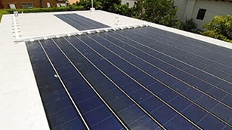
In 2017 my wife and I drove to South Carolina to witness the total solar eclipse. I have to say it is one of the coolest celestial events that I've witnessed in my life. At the time, I thought this was going to be a once-in-a-lifetime experience. But soon after that, I discovered that we would have another total solar eclipse in 2024. Well, here I am nearly seven years later, and I am super pumped that I get to see another total solar eclipse on April 8th!
This is going to be a simple project and I want you to build one so that we can all collect data on this event and share it together. I know I'm kind of a nerd when it comes to space and science, but I think it would be really cool for a whole bunch of people to collect data on the solar eclipse so that we can compare. I'm going to need a microcontroller for this project, and I decided to use the Adafruit ESP32 Reverse TFT Feather Board. The main thing that I want to be able to measure during a solar eclipse is the light level. I want to be able to measure what it is before, during, and after the event. To do this there are a couple of options. I could just get a simple photoresistor and put it into a voltage divider. Then I could read the analog voltage with an ADC pin on the microcontroller. The other option is to use a sensor like the SparkFun TEMT6000, which is an ambient light sensor. This device is very similar in that it outputs an analog voltage that I'll have to read with the microcontroller. And finally, I think it would be interesting to measure the temperature during the event. The cool thing about the ESP32 feather board is that it has a footprint for a BME280 temperature pressure and humidity sensor. They don't populate it to keep costs down. So, all I need to do is order that part from DigiKey and populate it myself. With all of these components, I'm able to capture the information that I need during the solar eclipse, but I also need a way to store this data. The ESP32 microcontroller can communicate over WiFi, so it's possible for me to stream this data from a web server on the microcontroller to my phone, but I don't necessarily want to rely on that in this situation. Instead, I’ll use an SD card and write all of the data to the card so that I have that as a backup.
So, to get started, I need to make a voltage divider circuit using the photoresistor that I can read with the microcontroller. I'm also going to connect up the SparkFun TEMT6000. Once I get that working, I can take the BME280, which is the temperature pressure and humidity sensor, and solder that to the board. Here is the circuit diagram for the photoresistor in the voltage divider. I basically need to put a photoresistor and a regular resistor in series between 3.3V and ground. The photoresistor I’m using has a range between 0 and 20k Ohms, so for the other half of the voltage divider, I decided to use a 1k resistor. If I measure between the two resistors, I'll get a varying output voltage that I can read using the ADC pin on my microcontroller. When it came time to connect the light sensor to the microcontroller, I decided to chop the end off of a servo extension cable. These cables are readily available and already have the three pins that I need. I put a little dab of CA glue and I secured the connector in place.
I wanted to create an enclosure for this project, so I went ahead and opened the CAD file for one that I designed last year for a different project. What I like about this design is that it has compliant button caps for each of the buttons. I just need to add a couple of extra holes in the side for the light sensor as well as the SD card. The other thing I like about this is that it has magnets built into the bottom so that it can attach to any metal surface like a car or a fence or a pole. I can either plug the light sensor directly into the side of the data logger, or I can use a servo extension cable to move the light sensor further away.
It's time to write some Arduino code for the microcontroller. I'm going to start by defining the pins that read the analog voltages coming in from the light sensor. Then I'll import the library for the BME280, and I'll start looking at an example for that so that I know how to use it and collect data. Now that I’m starting to collect data, I need to write that data to the SD card. The cool thing about the SD card module that I'm using is that it has a real-time clock on it. That means that I can put timestamps on every single measurement, and I don't have to worry about losing the time during power cycling. In order for the real-time clock to keep track of time, it needs a lithium coin cell battery. The real-time clock library has a built-in function that allows me to adjust and set the time. But when I followed the library example for setting the time, it used the compile time to set the real-time clock. By the time this code was uploaded to the microcontroller, it was already off by 30 or 40 seconds. Fortunately, I’m using an ESP32 Wi-Fi microcontroller, so I decided to set the current time using an NTP server. Network time protocol is used to synchronize computer clocks over a network. To set the time on my RTC I need to include some libraries and define some variables to store the time. In the setup function, I need to initialize the real-time clock. Then I write some code to connect to my Wi-Fi network. If I am successful in connecting to my network, I can begin the NTP client and ask it to update the time. The final step is to set the RTC based on the time received from the NTP server. Now my microcontroller is synchronized to the universal coordinated time, and the battery backup ensures my RTC will store this time for years even when my project is not powered.
The ESP32 Reverse TFT board has three buttons built in, which is one of the reasons why I really like this board. I set up three interrupt service routines, one for each button and then I display different information depending on which button was pressed. I'm hard coding the latitude and longitude values for the location where I'll be viewing the eclipse. If you're going to build this yourself, you'll need to update these values for your location. The code continuously captures data and averages the light values to help smooth out any noise from the ADC. Then once every second the data is written to the SD card in a comma-separated format. The code will create a new CSV file for every new day. If a file already exists for the day, new data is appended to the existing CSV file.
Now it's time to test the solar eclipse data logger. Now, since I can't recreate a solar eclipse here in my workshop, I did my best to approximate a point source of light, which means I just turned off all the lights except for one of them. To help me test this out I need to make a small moon out of cardboard. So, I've got the sun in the sky, the moon in my hand, and the data logger on my workbench. I'm powering the data logger using a USB cable and the DigiKey power bank. I can create a shadow using the moon, and I'll pass the shadow slowly over the light sensor. As I do this, I can see the light value decreasing quite a bit. The light values are being written to the SD card once a second. As I continue to pass the shadow over and it passes on the other side, the light value increases back to where it started.
Now we can pull the SD card out of the data logger and then plug it into the computer to open up that CSV file to see all the data. This is the kind of stuff that gets me excited! I love sensor data and I love spreadsheets! Now that I've got the SD card plugged into my laptop and I've opened it, I can see several files. I've been testing this over the last few days, so there are files for February 2nd, February 3rd, and February 4th, and then one for today which is February 5th. So, I'm going to open that one and let's see what it looks like. Look at all that data! That is so cool! The first column is latitude, then longitude, then the timestamp in the coordinated universal time, then the light value, then temperature in degrees Celsius. Now I want to copy and paste this into a spreadsheet program. It looks like I need to format this and split the text into columns. With the data more organized, now I can take the light values and graph them with respect to time. This is so exciting! I can see on the graph the times when I had the shadow of the moon in front of the light sensor and the values dip down and then they come back up. It doesn't get any better than this. I don't know what to tell you!
If you're planning to go see the solar eclipse this year and you want to build one of these data loggers, you're in luck. As with all of my projects, the design files for this are open source and will be available for download via GitHub. You can download the Arduino code as well as the 3D model for the enclosure. I hope you're as excited as I am to watch the solar eclipse this year, and if you do, make sure that you're wearing ISO-certified glasses to keep your eyes safe.