Mfr Part # 5800
EVAL BOARD FOR ESP32-S3
Adafruit Industries LLC
License: See Original Project 3D Printing LCD / TFT
Courtesy of Adafruit
Guide by Liz Clark
Overview
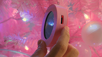
The Adafruit itsaSNAP app lets you use Apple Shortcuts to send data from your iOS device to your Adafruit IO feeds. Did you know that this includes photos? In this project, you'll setup an Apple Shortcut to use Base64 encoding to send a photo to your Adafruit IO feed. A Qualia S3 running CircuitPython code will retrieve the photo from the feed using MQTT, decode it and show it on a beautiful 720x720 round display.
You can setup the Shortcut to pull from a specific album in the Photos app, a period of time or even your most recent photo. Every time you run the Shortcut, the photo will be resized, encoded, and sent to your Adafruit IO feed with itsaSNAP. Once the new photo is sent to the feed, the Qualia S3 will update.
Parts
Text editor powered by tinymce.
3D Printing
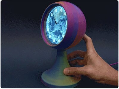
The photo display may be assembled with 3D printed parts, described below. The enclosure has three parts: a frame, a lid, and a mount.
The STL files can be downloaded directly here or from Printables.
Qualia_Picture_Frame_STL_Files.zip
The CAD source files can be downloaded from the link below:
Qualia_Picture_Frame_CAD_Files.zip
The frame has slots to fit the 720x720 display securely. The mount snap fits behind it.
The lid snap fits to close the frame. It has a cutout at the bottom for a USB cable. The mount has M3 mounting holes for the Qualia S3.
Text editor powered by tinymce.
Get Started with Adafruit IO
Adafruit IO is integrated with your adafruit.com account so you don't need to create yet another online account! You need an Adafruit account to use Adafruit IO because we want to make sure the data you upload is available to only you (unless you decide to publish your data).
I have an Adafruit.com Account already
If you already have an Adafruit account, then you already have access to Adafruit IO. It doesn't matter how you signed up; your account will make all three available.
To access Adafruit IO, simply visit https://io.adafruit.com to start streaming, logging, and interacting with your data.
Create an Adafruit Account (for Adafruit IO)
An Adafruit account makes Adafruit content and services available to you in one place. Your account provides access to the Adafruit shop, the Adafruit Learning System, and Adafruit IO. This means only one account, one username, and one password are necessary to engage with the content and services that Adafruit offers.
If you do not have an Adafruit account, signing up for a new Adafruit account only takes a couple of steps.
Begin by visiting https://accounts.adafruit.com.
Click the Sign Up button under the "Need An Adafruit Account?" title, below the Sign In section.
This will take you to the Sign Up page.
Fill in the requested information and click the Create Account button.
This takes you to your Adafruit Account home page. From here, you can access all the features of your account.
You can also access the Adafruit content and services right from this page. Along the top of the page, you'll see a series of links beginning with "Shop". To access any of these, simply click the link.
For example, to begin working with Adafruit IO, click the IO link to the right of the rest of the links. This is the same for the other links as well.
That's all there is to creating a new Adafruit account and navigating to Adafruit IO.
Text editor powered by tinymce.
Create an Adafruit IO Feed
Your Adafruit IO feed needs to have feed history turned off for this project to work.
Adafruit IO's main feature is creating feeds to write or read data in a centralized place. In this project, you will create an Adafruit IO feed to send and read weather data to.
In a web browser, navigate to io.adafruit.com/feeds and click "+ New Feed".
Name the Feed camera. The description is optional. Click Create to create the new feed.
Under My Feeds, you should see the camera feed you created. Click on it to view its settings.
Turn Off Feed History
In the side panel, go to Feed History and make sure it is turned Off.
If Feed History is not turned off, this project won't work because the value size will be limited to 1KB.
Text editor powered by tinymce.
CircuitPython
CircuitPython is a derivative of MicroPython designed to simplify experimentation and education on low-cost microcontrollers. It makes it easier than ever to get prototyping by requiring no upfront desktop software downloads. Simply copy and edit files on the CIRCUITPY drive to iterate.
CircuitPython QuickStart
Follow this step-by-step to quickly get CircuitPython running on your board.
This microcontroller requires the latest unstable (development) release of CircuitPython. Click below to visit the downloads page on circuitpython.org for your board. Then, Browse S3 under Absolute Newest.
Download the latest version of CircuitPython for this board via circuitpython.org
Click the link above to download the latest CircuitPython UF2 file.
Save it wherever is convenient for you.
The Qualia S3 does not have a RGB status LED
Plug your board into your computer, using a known-good data-sync cable, directly, or via an adapter if needed.
Double-click the reset button (highlighted in red above), and you will see the RGB status LED(s) turn green (highlighted in green above). If you see red, try another port, or if you're using an adapter or hub, try without the hub, or different adapter or hub.
This board does not have a NeoPixel, so you will need to just double tap the reset button.
For this board, tap reset and wait about a half a second and then tap reset again.
Some boards may not have a UF2 bootloader installed. If double-clicking does not work, follow the instructions on the "Install UF2 Bootloader" page in this guide.
If double-clicking doesn't work the first time, try again. Sometimes it can take a few tries to get the rhythm right!
A lot of people end up using charge-only USB cables and it is very frustrating! Make sure you have a USB cable you know is good for data sync.
You will see a new disk drive appear called TFT_S3BOOT.
Drag the adafruit_circuitpython_etc.uf2 file to TFT_S3BOOT.
The BOOT drive will disappear, and a new disk drive called CIRCUITPY will appear.
That's it!
Text editor powered by tinymce.
Create Your settings.toml File
CircuitPython works with WiFi-capable boards to enable you to make projects that have network connectivity. This means working with various passwords and API keys. As of CircuitPython 8, there is support for a settings.toml file. This is a file that is stored on your CIRCUITPY drive, which contains all of your secret network information, such as your SSID, SSID password and any API keys for IoT services. It is designed to separate your sensitive information from your code.py file so you are able to share your code without sharing your credentials.
CircuitPython previously used a secrets.py file for this purpose. The settings.toml file is quite similar.
Your settings.toml file should be stored in the main directory of your CIRCUITPY drive. It should not be in a folder.
CircuitPython settings.toml File
This section will provide a couple of examples of what your settings.toml file should look like, specifically for CircuitPython WiFi projects in general.
The most minimal settings.toml file must contain your WiFi SSID and password, as that is the minimum required to connect to WiFi. Copy this example, paste it into your settings.toml, and update:
your_wifi_ssid
your_wifi_password
CIRCUITPY_WIFI_SSID = "your_wifi_ssid"
CIRCUITPY_WIFI_PASSWORD = "your_wifi_password"
Many CircuitPython network-connected projects on the Adafruit Learn System involve using Adafruit IO. For these projects, you must also include your Adafruit IO username and key. Copy the following example, paste it into your settings.toml file, and update:
your_wifi_ssid
your_wifi_password
your_aio_username
your_aio_key
CIRCUITPY_WIFI_SSID = "your_wifi_ssid"
CIRCUITPY_WIFI_PASSWORD = "your_wifi_password"
ADAFRUIT_AIO_USERNAME = "your_aio_username"
ADAFRUIT_AIO_KEY = "your_aio_key"
Some projects use different variable names for the entries in the settings.toml file. For example, a project might use ADAFRUIT_AIO_ID in the place of ADAFRUIT_AIO_USERNAME. If you run into connectivity issues, one of the first things to check is that the names in the settings.toml file match the names in the code.
Not every project uses the same variable name for each entry in the settings.toml file! Always verify it matches the code.
settings.toml File Tips
Here is an example settings.toml file.
# Comments are supported
CIRCUITPY_WIFI_SSID = "guest wifi"
CIRCUITPY_WIFI_PASSWORD = "guessable"
CIRCUITPY_WEB_API_PORT = 80
CIRCUITPY_WEB_API_PASSWORD = "passw0rd"
test_variable = "this is a test"
thumbs_up = "\U0001f44d"
In a settings.toml file, it's important to keep these factors in mind:
Strings are wrapped in double quotes; ex: "your-string-here"
Integers are not quoted and may be written in decimal with optional sign (+1, -1, 1000) or hexadecimal (0xabcd).
Use \u escapes for weird characters, \x and \ooo escapes are not available in .toml files
Unicode emoji, and non-ASCII characters, stand for themselves as long as you're careful to save in "UTF-8 without BOM" format
When your settings.toml file is ready, you can save it in your text editor with the .toml extension.
Accessing Your settings.toml Information in code.py
In your code.py file, you'll need to import the os library to access the settings.toml file. Your settings are accessed with the os.getenv() function. You'll pass your settings entry to the function to import it into the code.py file.
import os

print(os.getenv("test_variable"))
In the upcoming CircuitPython WiFi examples, you'll see how the settings.toml file is used for connecting to your SSID and accessing your API keys.
Text editor powered by tinymce.
Code the Photo Display
Once you've finished setting up your Qualia S3 with CircuitPython, you can access the code and necessary libraries by downloading the Project Bundle.
To do this, click on the Download Project Bundle button in the window below. It will download to your computer as a zipped folder.
# SPDX-FileCopyrightText: 2024 Liz Clark for Adafruit Industries
#
# SPDX-License-Identifier: MIT

import time
import os
import ssl
import io
import binascii
import jpegio
import microcontroller
import wifi
import socketpool
import displayio
from adafruit_qualia.graphics import Graphics, Displays
import adafruit_minimqtt.adafruit_minimqtt as MQTT

aio_username = os.getenv("ADAFRUIT_AIO_USERNAME")
aio_key = os.getenv("ADAFRUIT_AIO_KEY")

print(f"Connecting to {os.getenv('CIRCUITPY_WIFI_SSID')}")
wifi.radio.connect(os.getenv("CIRCUITPY_WIFI_SSID"), os.getenv("CIRCUITPY_WIFI_PASSWORD"))
print(f"Connected to {os.getenv('CIRCUITPY_WIFI_SSID')}!")

camera_feed = aio_username + "/feeds/camera"

graphics = Graphics(Displays.ROUND40, default_bg=None, auto_refresh=True)

def center(g, b):
    # center the image
    g.x -= ((b.width * 2) - 720) // 4
    g.y -= ((b.height * 2) - 720) // 4

def decode_image(base64_msg):
    # Decode the base64 image into raw binary JPEG data
    decoded_image = binascii.a2b_base64(base64_msg)
    # Create a JpegDecoder instance
    decoder = jpegio.JpegDecoder()
    # Use io.BytesIO to treat the decoded image as a file-like object
    jpeg_data = io.BytesIO(decoded_image)
    # Open the JPEG data source from the BytesIO object
    width, height = decoder.open(jpeg_data)
    print(width, height)
    # Create a Bitmap with the dimensions of the JPEG image
    bitmap = displayio.Bitmap(width, height, 65536)  # Use 65536 colors for RGB565
    # Decode the JPEG into the bitmap
    decoder.decode(bitmap)
    # pylint: disable=line-too-long
    grid = displayio.TileGrid(bitmap, pixel_shader=displayio.ColorConverter(input_colorspace=displayio.Colorspace.RGB565_SWAPPED))
    center(grid, bitmap)
    group = displayio.Group(scale=2)
    group.append(grid)
    graphics.display.root_group = group
    graphics.display.refresh()


# Define callback methods which are called when events occur
def connected(client, userdata, flags, rc): # pylint: disable=unused-argument
    # This function will be called when the client is connected
    # successfully to the broker.
    print(f"Connected to Adafruit IO! Listening for topic changes on {camera_feed}")
    # Subscribe to all changes on the onoff_feed.
    client.subscribe(camera_feed)


def disconnected(client, userdata, rc): # pylint: disable=unused-argument
    # This method is called when the client is disconnected
    print("Disconnected from Adafruit IO!")


def message(client, topic, msg): # pylint: disable=unused-argument
    # This method is called when a topic the client is subscribed to
    # has a new message.
    print(f"New message on topic {topic}")
    decode_image(msg)

pool = socketpool.SocketPool(wifi.radio)
ssl_context = ssl.create_default_context()
# Initialize an Adafruit IO HTTP API object
mqtt_client = MQTT.MQTT(
    broker="io.adafruit.com",
    port=1883,
    username=aio_username,
    password=aio_key,
    socket_pool=pool,
    ssl_context=ssl_context,
)
# Setup the callback methods above
mqtt_client.on_connect = connected
mqtt_client.on_disconnect = disconnected
mqtt_client.on_message = message

# Connect the client to the MQTT broker.
print("Connecting to Adafruit IO...")
mqtt_client.connect()
while True:
    # Poll the message queue
    try:
        mqtt_client.loop(timeout=1)
        time.sleep(5)
    except Exception as error: # pylint: disable=broad-except
        print(error)
        time.sleep(5)
        microcontroller.reset()
Upload the Code and Libraries to the Qualia S3
After downloading the Project Bundle, plug your Qualia S3 into the computer's USB port with a known good USB data+power cable. You should see a new flash drive appear in the computer's File Explorer or Finder (depending on your operating system) called CIRCUITPY. Unzip the folder and copy the following items to the Qualia S3's CIRCUITPY drive.
lib folder
code.py
Your Qualia S3 CIRCUITPY drive should look like this after copying the lib folder and the code.py file.
Add Your settings.toml File
As of CircuitPython 8.0.0, there is support for Environment Variables. Environment variables are stored in a settings.toml file. Similar to secrets.py, the settings.toml file separates your sensitive information from your main code.py file. Add your settings.toml file as described in the Create Your settings.toml File page earlier in this guide. You'll need to include your ADAFRUIT_AIO_USERNAME, ADAFRUIT_AIO_KEY, CIRCUITPY_WIFI_SSID and CIRCUITPY_WIFI_PASSWORD.
CIRCUITPY_WIFI_SSID = "your-ssid-here"
CIRCUITPY_WIFI_PASSWORD = "your-ssid-password-here"
ADAFRUIT_AIO_USERNAME = "your-username-here"
ADAFRUIT_AIO_KEY = "your-key-here"
How the CircuitPython Code Works
At the top of the code, your Adafruit IO credentials are imported from the settings.toml file. A WiFi connection is established using your SSID and SSID password from the settings.toml file. The Adafruit IO feed that will be monitored via MQTT is passed to camera_feed. You can change the feed name here if you prefer to use a feed that isn't called "camera".
aio_username = os.getenv("ADAFRUIT_AIO_USERNAME")
aio_key = os.getenv("ADAFRUIT_AIO_KEY")

print(f"Connecting to {os.getenv('CIRCUITPY_WIFI_SSID')}")
wifi.radio.connect(os.getenv("CIRCUITPY_WIFI_SSID"), os.getenv("CIRCUITPY_WIFI_PASSWORD"))
print(f"Connected to {os.getenv('CIRCUITPY_WIFI_SSID')}!")

camera_feed = aio_username + "/feeds/camera"
Graphics
The 720x720 round display is instantiated using the adafruit_qualia library. Two functions are used for graphics. The first is a simple function called center() that centers the image on the display.
The second is called decode_image(). This function takes the Base64 encoded image from the Adafruit IO feed, decodes it using jpegio and displays it as a bitmap on the display.
You'll notice that the displayio group is set to scale=2. This lets you use a smaller image to stay within the data size limits of Adafruit IO feeds (100KB with no feed history) while still filling up the entire display. You'll see on the Apple Shortcut page that the images are being resized to a width of 360, half of 720.
graphics = Graphics(Displays.ROUND40, default_bg=None, auto_refresh=True)

def center(g, b):
    # center the image
    g.x -= ((b.width * 2) - 720) // 4
    g.y -= ((b.height * 2) - 720) // 4

def decode_image(base64_msg):
    # Decode the base64 image into raw binary JPEG data
    decoded_image = binascii.a2b_base64(base64_msg)
    # Create a JpegDecoder instance
    decoder = jpegio.JpegDecoder()
    # Use io.BytesIO to treat the decoded image as a file-like object
    jpeg_data = io.BytesIO(decoded_image)
    # Open the JPEG data source from the BytesIO object
    width, height = decoder.open(jpeg_data)
    print(width, height)
    # Create a Bitmap with the dimensions of the JPEG image
    bitmap = displayio.Bitmap(width, height, 65536)  # Use 65536 colors for RGB565
    # Decode the JPEG into the bitmap
    decoder.decode(bitmap)
    # pylint: disable=line-too-long
    grid = displayio.TileGrid(bitmap, pixel_shader=displayio.ColorConverter(input_colorspace=displayio.Colorspace.RGB565_SWAPPED))
    center(grid, bitmap)
    group = displayio.Group(scale=2)
    group.append(grid)
    graphics.display.root_group = group
    graphics.display.refresh()
MQTT
The MQTT setup portion of the code is based on the MQTT CircuitPython example. It sets up functions to subscribe to your Adafruit IO feed, disconnect from Adafruit IO and receive a new message from the subscribed feed. In the message() function, the decode_image() function is called, passing the msg data from the feed. mqtt_client is instantiated to use Adafruit IO as the broker and pass your Adafruit IO credentials.
def connected(client, userdata, flags, rc): # pylint: disable=unused-argument
    # This function will be called when the client is connected
    # successfully to the broker.
    print(f"Connected to Adafruit IO! Listening for topic changes on {camera_feed}")
    # Subscribe to all changes on the onoff_feed.
    client.subscribe(camera_feed)


def disconnected(client, userdata, rc): # pylint: disable=unused-argument
    # This method is called when the client is disconnected
    print("Disconnected from Adafruit IO!")


def message(client, topic, msg): # pylint: disable=unused-argument
    # This method is called when a topic the client is subscribed to
    # has a new message.
    print(f"New message on topic {topic}")
    decode_image(msg)

pool = socketpool.SocketPool(wifi.radio)
ssl_context = ssl.create_default_context()
# Initialize an Adafruit IO HTTP API object
mqtt_client = MQTT.MQTT(
    broker="io.adafruit.com",
    port=1883,
    username=aio_username,
    password=aio_key,
    socket_pool=pool,
    ssl_context=ssl_context,
)
# Setup the callback methods above
mqtt_client.on_connect = connected
mqtt_client.on_disconnect = disconnected
mqtt_client.on_message = message

# Connect the client to the MQTT broker.
print("Connecting to Adafruit IO...")
mqtt_client.connect()
The Loop
MQTT makes the loop very simple. mqtt_client.loop(timeout=1) with a slight delay is wrapped in a try/except to reset the board in case of any errors. Using this method, anytime a new photo is sent to your Adafruit IO feed, it will run the decode_image() function and update the display to show the new photo.
while True:
    # Poll the message queue
    try:
        mqtt_client.loop(timeout=1)
        time.sleep(5)
    except Exception as error: # pylint: disable=broad-except
        print(error)
        time.sleep(5)
        microcontroller.reset()
Text editor powered by tinymce.
Download the ItsaSnap by Adafruit App
This section will guide you through downloading and installing the ItsaSnap by Adafruit app.
Download and Install ItsaSnap
To install and download ItsaSnap for your iOS device,
You may be prompted to enter your Apple ID password or use Face ID/Touch ID to confirm the installation.
After you have downloaded and installed ItsaSnap, open the app.
You will need to enter your Adafruit username and Adafruit IO Key (which is different from your Adafruit account password).
Your Adafruit IO key is a long string of letters and numbers. To make it easier to add to the app, we've also included a QR code scanner that allows you to easily copy the Adafruit IO Key from the Adafruit IO website to the app.
On the ItaSnap app, the QR code scanner is located below the Adafruit IO Key and above the login button. To access it, press the 'Scan QR code for IO Key' button. This will open the QR code scanner.
To find the QR code for your Adafruit IO account, navigate go to the overview page. Once there, click the yellow button with a key in the center (it's next to the "New Device" button) to reveal your Adafruit IO Key.
After clicking it, a window with your information will appear. Then, find the QR code and scan it, and log in.
Text editor powered by tinymce.
"Send Photo to Adafruit IO" Apple Shortcut
You'll use Apple Shortcuts to encode your image from the Photos app to send it to an Adafruit IO feed with the itsaSNAP app. You can download the Shortcut via the link below or build it out yourself using the steps below.
Choose Your Photo Source
Select the Find Photos Where action to filter your photos by album, date, type, etc. For this example, I chose to focus on an album and then I randomized the photo choice by selecting Random under Sort by. You'll want to enable the Limit and make sure that Get 1 Photo is selected to send only one photo to Adafruit IO.
Next, the Convert Image action takes the Photo selected by the Find Photos Where action and converts it to a JPEG. You may need to experiment with the Quality slider. It should be set lower to stay within the size limits of an Adafruit IO feed. Make sure to turn off Preserve Metadata.
Get the Height and Width
The Set variable action is used to create an instance of the Converted image called Jpeg. This lets you reference the Converted image more easily throughout the Shortcut; similar to using variables in your CircuitPython or Arduino code.
The Get Details of Images action is used to get the Width of the Jpeg. Set variable is used again to create a variable for the Width. The same actions are used to get the Height of the Jpeg.
Check for Portrait vs. Landscape
This next part of the Shortcut is based on a Shortcut posted on the Shortcuts subreddit for discerning the orientation of an image. An If action checks if the Height is greater than the Width. If it is, then the image has a vertical/portrait orientation (3:4, 9:16, etc.). Otherwise, it has a horizontal/landscape orientation (4:3, 16:9, etc.). If the image is vertical, the Resize action changes the width to be 360 pixels. If the image is horizontal, the Resize action changes the height to be 360 pixels.
360 pixels is used so that the image will be small enough for an Adafruit IO feed and fill up the 720x720 display since the CircuitPython code is increasing the display group size by 2x.
Encode and Send
The last portion of the Shortcut uses the Encode action to encode the result of the If statement, aka the resized image, with base64. Make sure that Line Breaks is set to None. Finally, the itsaSNAP Send Value action is used to send the result of the Base64 Encoded image to your feed.
Text editor powered by tinymce.
Assembly
Insert the ribbon cable on the display into the ribbon connector on the Qualia S3. The display should be facing up and the Qualia S3 should have its components facing up.
Attach the Qualia S3 to the 3D printed mount with four M3 screws. The ribbon cable should be facing towards the flat edge of the mount.
Insert the display into the cutout in the 3D printed frame.
Carefully snap the mount into the tabs in the frame. This secures the display in its cutout.
Plug a USB C cable into the Qualia S3.
Close up the frame with the back lid. Run the USB cable through the cutout at the bottom of the lid.
Text editor powered by tinymce.
Use
Power up your Qualia S3 with the USB C cable. Open the Shortcuts app on your iOS device and run the Send Photo to IO Shortcut. You'll see a new photo appear on the display.
If you run into any errors, make sure that your Adafruit IO feed has feed history turned off as described on the Create an Adafruit IO Feed page in this guide.
Your Adafruit IO feed for this project needs to have feed history turned off for this project to work.
If you look at your feed in the itsaSNAP app, you'll see the encoded photo data.
If you look at your feed in the web viewer, you'll see the photo as well as the encoded data.
Experiment with different photo sets and filters to create your perfectly curated digital photo display. You can use Automations in Shortcuts to run the Shortcut at a specific time, when an app is opened, etc.
Text editor powered by tinymce.